
Semiconductor Equipment Plates and Brackets
This page is for mechanical engineers, buyers and supplier quality engineers sourcing machined plates, brackets and frames for semiconductor equipment modules.
Use it to decide which flatness, datum, surface and cleanliness requirements your drawing and specification must state for the part's installation location, and in what condition the part should be delivered.
Start with Where the Plate or Bracket Is Installed
A base plate under a robot, a sensor bracket inside the tool enclosure and a support inside a mini-environment can share material and geometry and still need very different requirements.

Mounting pads, dowel holes and a bracket leg on parts made to equipment drawings
Requirements added as a part moves closer to the process area — concept illustration
Location decides which surfaces face the process or the wafer path, which cleanliness or material restrictions apply and how the part must arrive. State that location in the request, even in general terms, before machining is discussed.
Requirements for a sensitive location come from your own specification or the standards it cites, not from the word semiconductor. A machined part is made and checked against what that specification states for the part, so the drawing and specification should say which requirements apply to this part number and which belong to other parts in the module.
Related: Semiconductor equipment parts
mounting faces, hole patterns, threads and an ordinary protective finish.
added attention to burrs, chips, residues and labelling near moving mechanisms.
the cleanliness, material and packaging requirements your specification states.
material, surface, trapped-volume and cleaning requirements for vacuum service.
Scope of this page
It describes how to define machined plates and brackets. It does not state that cleaning, vacuum preparation or any certification is included; those are agreed per order against your specification.
Flatness on Large Plates Depends on Stock, Support and Measurement
Flatness on a large, thin plate is shaped by more than the final cut.
One requirement on the whole face, or one shared zone on the pads only — concept illustration
Raised mounting pads machined on a large plate where the mechanism will sit
Residual stress in rolled plate, the amount of material removed from each side and the way the plate is clamped all influence how it lies once released. If the plate carries a robot, a stage or a sensor array, tell the review whether a stress-relieved plate, a cast tooling plate or another stock form is specified, and where the flatness requirement applies.
Flatness of a whole face and coplanarity of a few mounting pads are different requirements. Many designs only need the pads coplanar, which is easier to hold and to check than a full face. State the measurement condition too: free state on defined supports, or bolted to a reference. A flatness value without its condition can be measured in more than one way, and two honest reports can disagree.
Related: Quality and inspection
Area-specific callouts
If only the pads under a mechanism need the tight requirement, apply it to those pads as a common zone and leave the rest of the face to a general requirement.
Dowels, Hole Patterns and Threads on Mounting Plates
A mounting plate usually locates a mechanism with dowel holes and fastens it with a tapped pattern.

Dowels and primary face as references for the tapped pattern and slots — concept illustration
Reference the pattern to the dowels and the primary face, and say which holes are slotted for adjustment during alignment. When a mechanism is replaced in the field, the dowel positions let the new unit return to the same place, so they deserve the tight callouts more than the clearance holes do.
Tapped holes in aluminium plates may be fitted with thread inserts. State the insert type and part number, whether inserts are installed before or after finishing, and any hole that must stay without an insert. For brackets, show the perpendicularity or angle of each leg to the base face; a bracket that is correct in size but out of square tilts the sensor or actuator it carries.
Related: 5-axis machining · Automation fixtures and locating parts
Check Frame and Multi-Part Support Drawings
Equipment frames are often assembled from machined members, plates and brackets, or built as a weldment that is machined afterwards. Either way, the final references depend on the order in which features are made. Before the frame drawing goes out, check these points, because each one changes the route, the scope of the quotation and the inspection plan.
Machining after assembly
whether mounting faces are finished on the assembled frame or on each member before assembly.
Weldment scope
whether welding, stress relief and post-weld machining are in the quoted scope, and which standard and faces apply.
Frame datums
which pads or bores define the frame for the modules mounted on it.
Squareness and diagonals
the relationships between members you will check at installation.
Pins and fasteners
whether dowels and screws are supplied, and any torque or locking requirement.
Size and handling
overall size and mass for lifting points, packing and transport.
Material and Surface Requirements by Location
Material and surface requirements should follow the location, not a general label for the industry. A structural bracket may need only an alloy, a temper and a protective finish; a part near the wafer path or on the vacuum side may carry restrictions that your specification lists. Put each requirement on the drawing or reference the specification clause, so every part number carries its own set.
| Location | Requirements to state | Evidence to agree |
|---|---|---|
| Structural frame or external support | Alloy and condition, protective finish, threads and inserts | Dimensional report, and a material record if required |
| Inside the enclosure, near mechanisms | Edge and burr requirements, finish, chip and residue removal | Visual inspection criteria and any cleaning record specified |
| Mini-environment or wafer-handling area | Material restrictions, surface condition, cleaning and packaging per your specification | The cleaning or particle record your specification calls for |
| Vacuum side, if applicable | Material, surface texture, trapped volumes, cleaning and handling after cleaning | The verification method and record agreed for each requirement |
Restricted fluids and materials
If your specification limits cutting fluids, lubricants, marking inks or tapes that may touch the part, list them at quotation. Changing them later can change the whole route.
Edges, Burrs, Tool Marks and Blind Holes
Burrs at intersecting holes and thread entries, and chips left in blind holes, can later come loose as particles inside the equipment or damage a mating thread.
A cross-hole intersection and thread entry, the edges a burr requirement has to reach
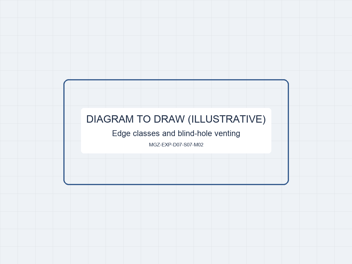
Edge classes, a trapped volume and a vented alternative — concept illustration
State the edge requirement for each class of edge rather than one general note, and say whether cross-holes and thread entries need inspection beyond a visual check. A tool mark on a sealing or contact face is judged by that face's surface requirement, which should state the parameter and, where relevant, the lay direction.
Blind tapped holes trap fluids and particles that cleaning may not reach, and on the vacuum side they also trap gas behind a screw. If your design rules call for through holes, vent holes or vented screws, show them on the drawing. Where blind holes remain, state how they are to be cleaned and inspected, so the requirement is visible at quotation rather than discovered at receiving.
Cosmetic versus functional
Separate cosmetic marks on outer faces from surface texture on contact or sealing faces. Each is accepted under its own criterion, and usually only the functional one needs a measured record.
Cleanliness Requirements Stated by Your Specification
Cleanliness can mean several different things: no visible chips or residue, removal of machining fluids, a particle result on a defined surface, or a cleaning sequence for vacuum service.
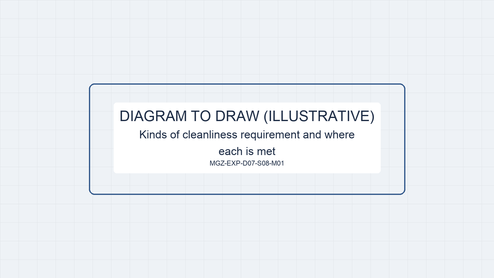
Four kinds of cleanliness requirement set against process stages — concept illustration
A machined part bagged and labelled for handover to the next cleaning step
Each has its own method and record. State which one applies to this part number, the specification and revision that defines it, and the stage at which it must be met, such as after machining, after finishing or after final cleaning.
Final cleaning for sensitive locations is often done by your own facility or a cleaning provider you appoint. In that case, the machined part's requirement is the condition in which it is handed over: free of chips and fluids to an agreed level, protected and labelled for the next step. Writing that handover condition down prevents each party from assuming the other one cleans.
Related: Semiconductor equipment parts
Define the Supplied Condition Step by Step
The supplied condition is a sequence of steps, and each one has an owner. Writing them down in order shows where machining ends, which treatments are included and who holds the part at each stage. The steps below are a template for that conversation; your specification decides which of them apply to a given part number.
Machined and deburred: edges, cross-holes and threads finished to the drawing, with chips and fluids removed to the agreed level.
Finished: anodizing, passivation or another treatment, with masked areas and the provider named if it is outside the machining scope.
Cleaned: the cleaning step your specification calls for, or a note that final cleaning is done by you or your provider.
Protected and packed: bagging, face protection and caps as specified, and the order in which parts are wrapped.
Labelled: part number, revision, quantity and lot on each pack, with the documents that travel with it.

A machined and deburred plate before any finishing or cleaning step

A finished bracket with the masked areas the order specified
A pack label and delivery list carrying part number, revision, quantity and lot
Name the owner of each step
A step without an owner is the one most likely to be missed or done twice. List each step with the party responsible for it.
Records That Match Each Requirement
Each requirement needs its own evidence. A dimensional report covers the listed features under the stated measurement condition; a material record covers the alloy and condition for the stated lot; a finish record covers the process and its parameters; a cleaning or particle record covers only the method and surface it names. Agree which records come with the order before production, not at receiving.
Every record should carry the part number, drawing revision and the lot or batch it covers, and the delivery list should show how many parts each record applies to. If the parts move on to another provider for cleaning or coating, ask for the records that travel with them and the condition in which they leave, so the next party starts from a known state.

A material record whose lot reference matches the part labels in the delivery
Conformance statements
A general certificate of conformance does not replace the specific records your specification asks for. Ask which requirements it covers and what evidence it is based on.
Compare Quotations on the Same Supply Condition
Quotations for the same plate can describe different deliveries: machined only, machined and finished, or finished, cleaned and packed to a specification. Before comparing prices, confirm that each quotation covers the same revision, stock form, finish, cleaning stage, records and packing, and that any specialist step done by another provider is shown as such.
| Compare | What to check in each quotation |
|---|---|
| Part definition | Drawing and specification revision, alloy, condition and stock form |
| Flatness approach | Stock form or stress relief assumed, and how flatness is measured and reported |
| Finish and cleaning | Which steps are included, which are done by another provider and which are left to you |
| Records | Dimensional, material, finish and cleaning records named in the quotation |
| Packing and labelling | Protection, bagging and labels as specified, and the documents that travel with the parts |
| One-time preparation | Programming, fixtures and first-article inspection, shown apart from the unit price |
Equipment Plate and Bracket Questions
Does every plate or bracket for semiconductor equipment need cleanroom packaging?
No. Packaging follows the installation location and your specification. A frame member or external support may need only ordinary protection and clear labels, while a part for a mini-environment or the vacuum side may need specific bagging and handling. State the packaging requirement per part number so the quotation does not apply the most demanding level to every part.
How should flatness be specified on a large mounting plate?
Apply the requirement where the function needs it, often to the mounting pads as a common zone, and state the measurement condition: free state on defined supports, or bolted to a reference. Mention any stock form or stress relief your design specifies. A clear condition lets the manufacturing review plan the stock, the sequence and the check together.
Can a machined bracket be delivered ready for a vacuum chamber?
That depends on what your specification requires and what is agreed for the order. Vacuum service often brings material, surface, venting, cleaning and post-cleaning handling requirements. List them at quotation and ask which steps are included and which are done by a specialist provider, so the delivered condition and its records are clear before the order is placed.
Which records should we ask for with a mounting plate?
Ask for the records your acceptance needs: a dimensional report for the dowels, pads and flatness under the stated condition, the material record for the lot, and the finish record if the finish affects fit or exposure. Add cleaning or particle records only where your specification requires them, and check that each record names the part number and revision.
Our specification is confidential. What can we send first?
Describe the part, its installation location in general terms, the quantity and the kind of surface, cleanliness and packaging requirement that applies. That is enough for a first discussion of scope. The full drawing and specification can be exchanged once confidentiality terms are agreed, and the quotation then refers to their revisions.
Discuss Your Equipment Plate or Bracket
Tell us where the part is installed, which faces carry the mechanism and which flatness, surface or cleanliness requirements apply.

Sales contact (pending)
Name, role and photo to be confirmed
Drawings are optional for an initial discussion.
Start with the information you have; file exchange can be arranged afterward.
Name to be confirmed
Sales, company name to be confirmed
- Add the quantity and the condition in which the part should be delivered.
- A short description is enough to start; drawings and specifications can follow once file exchange is agreed.
Project Inquiry
Fields marked are required.